
Abstract
We provide here detailed electrophysiological protocols to study voltage-gated sodium channels and to investigate how wild-type and mutant channels influence firing properties of transfected mammalian dorsal root ganglion (DRG) neurons. Whole-cell voltage-clamp recordings permit us to analyze kinetic and voltage-dependence properties of ion channels and to determine the effect and mode of action of pharmaceuticals on specific channel isoforms. They also permit us to analyze the role of individual sodium channels and their mutant derivatives in regulating firing of DRG neurons. Five to ten cells can be recorded daily, depending on the extent of analysis that is required. Because of different internal solutions that are used in voltage-clamp and current-clamp recordings, only limited information can be obtained from recording the same neuron in both modes. These electrophysiological studies help to elucidate the role of specific channels in setting threshold and suprathreshold responses of neurons, under normal and pathological conditions.
Introduction
Voltage-gated ion channels underlie action potential initiation and propagation in eukaryotic excitable membranes. Thus, determination of biophysical properties of individual channel isoforms can lead to a better understanding of the contribution of these channels to electrogenesis in the cells that house these channels. However, published studies have provided compelling examples of cell-type-specific effects on voltage-gated ion channels such as sodium channels, e.g., the Nav1.6 sodium channel has been shown to be the main source of a resurgent current1 in response to repolarization after depolarization to positive potentials in cerebellar Purkinje cells, but this current is not produced by Nav1.6 in hippocampal CA3 neurons2. Similarly, resurgent sodium current has been recorded from large- but not small-diameter neurons of dorsal root ganglion (DRG), even though both groups of cells express Nav1.6 (ref. 3). Nav1.8 (refs. 4,5,6) exhibits different slow inactivation properties in two distinct groups (IB4+ and IB4−) of DRG neurons, and these different properties endow these two groups of neurons with distinct firing properties7. Importantly, sensory and autonomic symptoms of an autosomal-dominant painful sodium channelopathy, which is caused by mutations in Nav1.7, inherited erythromelalgia8, appear to be explained by the differential response of sensory (DRG) and sympathetic ganglion neurons, e.g., superior cervical ganglion (SCG), to the expression of the same mutant Nav1.7 sodium channel9. These examples underscore the need to study the functional properties of sodium channels within the cells in which they are normally expressed.
Here we describe protocols that can be used to study sodium channels in mammalian DRG neurons, including those transfected by biolistics or electroporation, as described in our accompanying protocol10. We describe how to perform whole-cell voltage-clamp recordings from DRG neurons to obtain accurate measurements of the voltage-dependent and kinetic properties of ion channels in their native environment. This provides, e.g., information about the voltage range at which particular channels in DRG neurons activate as well as how fast the channels might activate under different conditions that mimic pathological states. We also describe how to perform current-clamp recordings in neurons to obtain information about firing properties of DRG and SCG neurons, e.g., how channels with inherited disease mutations impact the excitability and action potential generation in these neurons. This information can at best only be estimated using other techniques (such as computer modeling) and heterologous expression systems.
Voltage-clamp recording
Whole-cell voltage clamp. Voltage-clamp protocols (see Box 1 for a glossary) used with recombinant sodium channels expressed in neurons are generally similar to those used when recording from channels expressed in heterologous cell lines, but because native neurons in culture tend to grow neurites, special attention must be paid to space clamp. Although the following sections will provide advice on aspects of patch-clamp studies, a more comprehensive discussion of this powerful technique can be found in other publications11,12,13.

Preparation of neurons for voltage clamp
As noted in the protocol on transfection of neurons10, most neurons co-express multiple isoforms of sodium channels, making it difficult to discriminate, in isolation, the current produced by the channel isoform of interest. For most types of neurons, this problem can be obviated by transfecting with a tetrodotoxin-resistant (TTX-R) version of the channel of interest and then exposing the cells to 250–300 nM TTX during voltage-clamp recording, so as to block the other endogenous TTX-sensitive (TTX-S) sodium channels, leaving the current from the channel of interest in isolation14. The situation is more complex for DRG neurons, which express two TTX-R sodium channel isoforms, Nav1.8 and Nav1.9. The problem is circumvented by two maneuvers: (i) the use of DRG neurons from Nav1.8−/− mice15, which lack endogenous Nav1.8 channels; (ii) maintenance of the cells in culture for several days without glial-derived neurotrophic factor (GDNF), which reduces the level of Nav1.9 expression16,17, and holding the cells at −80 mV, a potential at which ultraslow inactivation abolishes any residual Nav1.9 current18.
Passive current components (linear leak currents and capacitive currents) are subtracted from the measured currents by recording a series of scaled voltage pulses just before, or after, the voltage pulse used to elicit voltage-gated sodium currents. These scaled pulses are typically one-fourth or one-fifth the amplitudes of the experimental pulses, and the subtraction process is referred to as P/4 or P/5 leak subtraction. Care must be taken in the design of the leak subtraction protocol. Initiation of the scaled subtraction pulses from a relatively negative holding potential and the use of a negative P/4 or P/5 protocol can ensure that the leak subtraction pulses do not inadvertently elicit voltage-dependent currents. It is important to include sufficient time between the leak pulses and the experimental pulse to ensure that the leak subtraction protocol is not inadvertently altering the sodium channel properties (e.g., by changing the proportion of channels that are fast- or slow-inactivated).
The voltage-gated sodium channel isoforms that are expressed in sensory neurons can exhibit dramatically different voltage-dependent and gating time courses, and therefore the voltage protocols used for specific sodium channels must be designed carefully. For example, Nav1.7 channels exhibit slower closed-state inactivation than Nav1.6 (ref. 19), and although a 100-ms inactivating prepulse may be appropriate for measuring steady-state fast-inactivation voltage-dependence for Nav1.6, 300 or 500 ms inactivating prepulses are required for Nav1.7. Similarly, although 50 ms depolarizing pulses are typically sufficient for recording the time course of Nav1.6 or Nav1.7 current activation and inactivation, they are not long enough to adequately record the slower inactivation kinetics of Nav1.9 channels.
Voltage-gated sodium currents can exhibit fast kinetics and adequate measurement of their gating properties requires a fast patch-clamp amplifier and a high-speed digitizer (typically, digitizing at 20 kHz and filtering (low-pass) at 5 kHz are used, but for accurate measurement of activation and deactivation time constants, it is better to digitize the data at 40 or 50 kHz and filter at 10 kHz). Voltage-clamp amplifiers with high-quality series resistance compensation and fast response times (∼10 μs), such as those manufactured by HEKA Electronics and Axon Instruments, are especially important for voltage-gated sodium channels in sensory neurons.
Single-channel recording. Sensory neurons are very amenable to recording currents using cell-attached, inside-out or outside-out patches20,21,22,23. However, the high density of sodium channels, especially in the outside-out configuration, can make it difficult to obtain patches with single channels. Thick-walled pipette glass seems to work best for manufacturing electrodes with small pipette tips and low capacitance. Coating of the glass with Sylgard or wax can lower the capacitance. Endogenous sodium channel activity can be eliminated using the same strategies used with the whole-cell recordings, as described above, so that recombinant single-channel properties can be analyzed in isolation.
Artifacts and pitfalls. A source of concern when recording any type of ion channel activity is that the gating properties can change during the recording period. Time-dependent changes in current properties can occur for a number of reasons, including dilution of specific modulators due to diffusion of the recording pipette or the activation of second messenger pathways by components of the pipette solution. Some of these changes can be minimized by careful design of pipette solutions (e.g., GTP-γS can help stabilize some ionic currents) or controlled for by running time-dependent controls and starting specific protocols at consistent times after establishing the whole-cell recording configuration.
The quality of voltage clamp is a major concern when recording sodium currents from neurons. Voltage-clamp errors can result from large sodium currents and high access resistances. Very large sodium current densities (>1 nA/pF) can be a problem when recombinant channels are expressed in adult neurons (Fig. 1). While lowering the extracellular sodium concentration, reducing the electrochemical gradient and effectively decreasing sodium current amplitudes can improve the quality of the voltage clamp, changes in sodium flux can alter gating properties such as slow inactivation or resurgent current properties. Alternatively, quality of the voltage clamp can be enhanced using low-resistance recording pipettes (<1 MΩ) and adequate series resistance compensation (Box 1). We have found that with a final access resistance of 1 MΩ and 85% series resistance compensation, we can reliably record sodium currents in DRG neurons with whole-cell amplitudes up to 35 nA. Other important factors include quality of the seal and stability of the recordings.

(a) Family of sodium current traces recorded from an adult DRG Nav1.8-null neuron expressing recombinant Nav1.6R channels showing adequate voltage control. (b) Peak current–voltage relationship from currents shown in panel a. Note that the current amplitude increases in a graded manner with voltage between −40 and −10 mV. (c) Family of sodium current traces recorded from an adult DRG Nav1.8-null neuron expressing recombinant Nav1.6R channels with inadequate voltage control. (d) Peak current–voltage from relationship from currents shown in panel c. Note that the current amplitude increases precipitously between −45 and −35 mV, indicating loss of voltage control. (e) Family of sodium current traces recorded from an adult DRG Nav1.8-null neuron expressing recombinant Nav1.6R channels illustrating inadequate space clamp. (f) Peak current–voltage from relationship from currents shown in panel (e). Note that at negative potentials (between −75 and −45 mV), sodium currents are activated with substantial delays, characteristic of the activation of sodium channels in neurites that are not adequately voltage-clamped. Dashed line in panels d and f shows the current–voltage data from panel b for comparison. All recordings were obtained in the presence of 300 nM TTX to block endogenous TTX-S sodium channels.
The use of fluoride in the pipette can greatly enhance the ability to perform long-term (>15 min) recordings of sodium currents from DRG neurons. Although fluoride can enhance the seal between the pipette and the cell membrane, it can increase time-dependent shifts in the voltage-dependent properties of some (but not all) sodium current subtypes; e.g., fluoride-based pipette solutions cause a significant hyperpolarizing shift in the gating of Nav1.9 but not Nav1.8 sodium currents24,25. Fluoride can also chelate calcium, inhibit phosphatases and alter the activity of second messenger systems including some kinases and G-proteins26,27,28,29,30,31. Fluoride-based solutions could be used to study modulation of sodium channels when cells are pretreated with the desired activator/inhibitor and the effect is determined by comparing treated with non-treated neurons. However, studying the effect of activation of signal transduction pathways on channels in real time, e.g., before and after addition of tyrosine kinase receptor ligands or activators of G-protein-coupled receptors, is best performed in non-fluoride-based pipette solutions, or interpreted cautiously when fluoride-based pipette solutions are used. Solutions containing aspartate and chloride as the main anions are generally good for these assays, and permit recordings lasting up to 15 min, but DRG neurons generally become leaky rather quickly if they are hyperpolarized to negative potentials (<−80 mV) for extended durations (>2 s) without fluoride in the intracellular solution. Thus, the composition of the intracellular and extracellular solutions must be chosen with care depending on the goals of the particular experiment.
Another source of problems with whole-cell voltage-clamp recordings from cultured sensory neurons is that these neurons can have extensive processes. Activity of channels in the neurites can be difficult to control because it is not possible to completely control the voltage in the neurites (Fig. 1e). Interestingly, we have found this to be more of a problem with endogenous currents than with recombinant channels under the conditions used in our studies. This may be due to a time lag between insertion of channels in the soma membrane and transport of channels to neurite membranes. If this is a major problem, the growth of neurites needs to be minimized. Limiting the time in culture can help. Transfection or infection of neurons with recombinant channels in vivo 1–2 d before harvesting the DRG might be the most effective approach. Alternatively, using substrates that inhibit or retard neurite outgrowth, or replating neurons a day before patching, may be helpful.
Current-clamp recording. Cellular transfection techniques have often been developed to maximize the transfection efficiency. Although this may be a desirable aim for many users of transfection, for electrophysiological recording, the health of the cells is paramount; the proper balance has to be reached between adequate ion channel expression and health of transfected cells. This is especially true when attempting to record from transfected native cells and, in particular, being able to successfully record action potential behavior using current clamp. At all times, the aim is to preserve the original cellular integrity but to allow adequate expression of the ion channel(s) of interest. Transfection by electroporation has proved to be the most successful method and the best compromise. Details of how to transfect by electroporation and a more extensive discussion of the technique can be found in Dib-Hajj et al.10.
Current-clamp recording from DRG neurons has typically been carried out on the same day of isolation. Studying native DRG neuron firing by current clamp after 24 h in culture is more challenging than acutely isolated neurons, although both TTX-S and TTX-R currents can be studied by voltage-clamp methods in these cultures (see above). Studying action potential firing in transfected neurons can only be undertaken after >24 h in culture to allow adequate expression of recombinant channels. We found that supplementing the culture media with nerve growth factor (NGF) and glial cell-line-derived neurotrophic factor (GDNF) (see Experimental Design) was necessary to reproducibly record action potentials in transfected DRG neurons, which is consistent with the published data that NGF and GDNF are necessary to maintain the expression of Nav1.8 and Nav1.9 channels in cultured DRG neurons16,17, and NGF also regulates the expression of Nav1.7 channel32,33.
Artifacts and pitfalls when using transfected neurons. One of the most important factors in obtaining good, consistent current-clamp recordings from transfected neurons is the cultures themselves. It is vital that high-quality cultures are maintained at all times, to allow sufficient healthy cells to survive the transfection process. It helps if the personnel involved routinely performs these tasks and with that, the processing time can be reduced to an absolute minimum. Using well-tested materials is also important, in particular the medium used for maintaining the cells in culture; media and sera can vary across batches; hence, it is important to validate and purchase sufficient quantities to complete a given study. Full testing of new medium stocks has also proved to be helpful, even to the extent of completing some electrophysiological recording to examine normal and expected expression of specific ion channels and also to show successful current-clamp recordings with the new reagents.
As mentioned earlier, once successful transfections have been achieved, selecting the cell for recording is important. If a cell displays an extremely bright green fluorescent protein fluorescence, this can often indicate that the cell is no longer healthy. Selecting healthy neurons that express the desired recombinant channels comes with experience and will vary depending on the particular preparation being used. However, using DRG and SCG cultures, quality recordings usually come from the cells showing an even fluorescent signal across the membrane, without a punctuate distribution. If the cell has balled up or is too rounded, or is not reasonably well attached to the coverslip or dish, the likelihood of a good recording is low. Another consideration is cell size. For example, with DRG neurons, there are major differences in sodium channel expression depending on the size of the cell body, which will affect firing behavior34. For comparisons of different transfected ion channels, it is essential to use narrow ranges of cell size for recordings, so that any differences are not masked by variations in endogenous currents.
Once a cell has been selected for recording, priority shifts to the patch-clamp electrode. As described above for voltage-clamp recordings, electrodes must have as low a resistance as possible. In our hands, the resistance of the electrodes for current-clamp recordings need to be slightly higher (∼2–3 MΩ) than that used for voltage-clamp studies, in order to obtain high-quality seals for stable recording. Sometimes it is necessary to allow 1–3 min for the seal to develop to its full potential before rupturing the patch. However, taking the pipette resistance too high can lead to input resistance problems and clogging of electrode during recording.
Experimental design
Some of the following points should be considered before starting an experiment.
-
1
For voltage-clamp recordings of the TTX-R version of sodium channels, the Nav1.8-null mouse4, or knockdown of Nav1.8 with shRNA, is required. Alternatively, transfection of SCG neurons can be attempted because these neurons do not have endogenous TTX-R channels.
-
2
Design the voltage-clamp protocols carefully to examine different aspects of channel gating. A standard characterization of channel gating may use different pulse protocols to examine different gating properties of sodium channels. Problems related to inadequate space-clamp or voltage-clamp errors can be readily identified using a standard activation protocol where current is activated with voltage depolarizations ranging from −80 to 40 mV (Fig. 1).
-
3
For voltage-clamp recordings, do not supplement the DRG media with the exogenous trophic factors, NGF and GDNF, because they will upregulate the expression of the endogenous TTX-R channels, Nav1.8 and Nav1.9, and hinder the analysis of the recombinant TTX-R channel that is transfected into DRG neurons. In addition, these trophic factors stimulate the formation of neurites that contribute to space-clamp problems that hinder the analysis of gating properties of sodium currents.
-
4
For current-clamp recordings, DRG media should be supplemented with the trophic factors, NGF and GDNF, to ensure optimal expression of all sodium channels in transfected DRG and to record successfully from neurons in culture for more 24 h.
Example application. Current-clamp recordings can provide useful information about the contribution of a channel to resting membrane potential (RMP), and to spontaneous and evoked firing patterns that may be specific to the cell type under study. An example is presented by the erythromelalgia Nav1.7-L858H mutation, which was investigated by our laboratory9, as discussed next.
Nav1.7 is normally expressed in both sensory DRG neurons and sympathetic SCG neurons (Table 1s in Dib-Hajj et al.10) and it is important to examine the effects of the mutated channel on firing behavior of both types of neuron. Voltage-clamp experiments indicate that the mutation shifts the voltage dependence of activation in a hyperpolarized direction and enhances the current in response to small, slow depolarization (ramp current)35. Moreover, using current-clamp recordings it is possible to show that the mutant channel has opposing effects on excitability of the two types of neurons. These recordings show that the mutant channel produced a 5-mV depolarization in RMP in both cell types. However, the mutant channel produces hyperexcitability (decreased current threshold for single action potentials; increased firing frequency in response to suprathreshold stimulation) in DRG neurons (Fig. 2a–c) and hypoexcitability (Fig. 2d–f) (increased current threshold for single action potentials; decreased firing frequency in response to suprathreshold stimuli) in SCG neurons. This is due, at least in part, to the selective presence of the sensory neuron-specific Nav1.8 sodium channel, which is relatively resistant to inactivation by depolarization4,6,36, in DRG neurons, and its absence in SCG neurons9.

(a) Representative DRG neuron expressing WT Nav1.7 fires a single action potential in response to a 950-ms input of 100 pA from the RMP of this neuron (approximately −50 mV). The same neuron fires multiple action potentials in response to a 250-pA stimulus (inset). (b) Representative DRG neuron expressing L858H fires five action potentials in response to a 100-pA current injection from RMP of this neuron (∼−42 mV). (c) For the entire population of DRG neurons studied, the firing frequency evoked by 50 pA current stimuli was 0.32 ± 0.13 Hz after transfection with WT channels (n = 20) and 2.06 ± 0.79 Hz after transfection with L858H (n = 24; P < 0.05), and the firing frequency evoked by 100 pA stimuli was 0.89 ± 0.28 Hz after transfection with WT and 3.37 ± 1.13 Hz after transfection with L858H (P < 0.05). (d) Representative SCG neuron expressing WT Nav1.7 fires six action potentials in response to a 950-ms input of 40 pA from RMP (approximately −45 mV). (e) Representative SCG neuron expressing L858H fires only two action potentials in response to a 100-pA current injection from RMP (approximately −40 mV). When the cell was held at −60 mV to overcome the depolarization of RMP caused by L858H, it produced four action potentials with an identical stimulus. (f) For the entire population of SCG neurons studied, the firing frequency evoked by 30 pA stimuli was 5.33 ± 1.5 Hz after transfection with WT channels (n = 14) and 0.63 ± 0.01 Hz after transfection with L858H channels (n = 15; P < 0.05); firing frequency evoked by 40 pA stimuli was 7.05 ± 1.86 Hz after transfection with WT and 1.96 ± 1.0 Hz after transfection with L858H channels (P < 0.05). Adapted with permission of Rush et al.9.
Materials
Reagents
-
DRG neurons isolated from rats or mice growing on coverslips (see Dib-Hajj et al.10 for details of how to isolate and, if desired, to transfect DRG neurons)
Caution
Use of rodents must conform to appropriate national and institutional regulations.
-
DRG medium: D-MEM/F-12 (1:1, vol/vol) (Invitrogen)
-
Fetal bovine serum (Hyclone)
-
Penicillin/streptomycin (Invitrogen)
-
Low melting point pipette glass (World Precision Instruments)
-
Cesium flouride, CsF (Sigma-Aldrich)
-
Cesium chloride, CsCl (Sigma)
-
Sodium chloride, NaCl (Sigma)
-
Potassium chloride, KCl (Sigma)
-
Magnesium chloride, MgCl2 (Sigma)
-
Calcium chloride CaCl2 (Sigma)
-
Cadmium chloride CdCl2 (Sigma)
-
Tetra ethyl ammonium chloride, TEA-Cl (Sigma)
-
Choline chloride, Choline-Cl (Sigma)
-
EGTA (Sigma)
-
Mg-ATP (Sigma)
-
HEPES buffer (Sigma)
-
Glucose (Sigma)
-
Tetrodotoxin, TTX (Sigma)
Equipment
-
Inverted microscope with fluorescence, e.g., Nikon TE2000 w/fluorescence (Nikon)
-
Narishige MF-830 microforge (Narishige International USA)
-
Origin software (OriginLab Corporation)
-
Patch-clamp amplifier: Axopatch 200B (Molecular Devices)
-
Patch-clamp amplifier: EPC-9 or EPC-10 amplifier (HEKA Electronics)
-
PDMI-2 Micro-Incubator and Temperature Controller TC-202A (Harvard Apparatus)
-
Precision micromanipulator and microscope mounting adaptors (EXFO)
-
Relay rack enclosure (Allied Electronics)
-
Software and data acquisition interface, e.g., pCLAMP Digidata 1440A (Molecular Devices) or Pulse and PulseFit (HEKA Electronics).
-
Sutter P-97 programmable pipette puller (Sutter Instrument Company)
-
Vibration isolation table and perimeter Faraday cage (TMC)
Reagent setup
Pipette (internal) solution for voltage-clamp recordings
-
Prepare (in mM): 140 CsF, 10 NaCl, 2 MgCl2, 0.1 CaCl2, 1.1 EGTA (pCa = 8), 10 HEPES. Adjust pH to 7.2 with CsOH. Adjust osmolarity to 310 mosM with glucose. Pipette solution can be stored at 4 °C until needed.
Bath (extracellular) solution for voltage-clamp recordings
-
Prepare (in mM): 140 NaCl, 3 KCl, 1 MgCl2, 1 CaCl2, 10 glucose and 10 HEPES. Adjust pH to 7.3 using NaOH. Adjust osmolarity to 320 mosM liter−1 with glucose.
Critical
To isolate TTX-R currents, add to the bath solution: 20 mM TEA-Cl (blocks voltage-gated K+ channels), 0.1 mM CdCl2 (blocks voltage-gated Ca2+ channels) and 300 nM TTX (blocks >95% of voltage-gated TTX-S sodium channels).
Critical
To avoid voltage-clamp errors when recording very large sodium currents (>10 to 15 nA), decrease the sodium current amplitude by reducing the Na+ gradient using a mixture of 70 mM NaCl and 70 mM Choline-Cl (or even 35 mM NaCl and 105 mM Choline-Cl) in the bath solution instead of 140 mM NaCl.
Pipette (internal) solution for current-clamp recordings
-
Prepare (in mM): 140 KCl, 0.5 EGTA, 5 HEPES and 3 Mg-ATP. Adjust pH to 7.3 with KOH. Adjust osmolarity to 300 mosM with glucose. Aliquot and store the solution at −20 °C until needed.
Critical
Do not freeze–thaw the pipette solution.
Bath (extracellular) solution for current-clamp recordings
-
Prepare (in mM): 140 NaCl, 3 KCl, 2 MgCl2, 2 CaCl2 and 10 HEPES. Adjust pH to 7.3 with NaOH. Adjust osmolarity to 315 mosM with glucose. Store at 4 °C until needed.
Equipment setup
Preparation of coated coverslips
-
This is an alternative to using commercially available precoated (poly-D-lysine/laminin; coverslips (BioCoat, BD Biosciences)). First, clean and store 12-mm-circular glass coverslips in 95% (vol/vol) ethanol. Flame the coverslips to burn off the alcohol and place them in wells of a 24-well plate. Coat each coverslip with 100 μl of poly-L-ornithine solution (0.1 mg/ml in 15 mM borate buffer, pH 8.4) and leave at room temperature (∼21 °C) for 20 min to 1 h. Aspirate off the poly-L-ornithine solution and rinse the coverslips twice with sterile de-ionized water. Allow coverslips to dry completely under the hood (at least 15 min or overnight). Spread the 2.5-μl laminin solution (5 μg/ml) on each coverslip with a flattened pipette tip and allow the coverslips to dry completely. Sterilize the coverslips with UV light for 10 min before plating the cells.
Preparation of optimal patch pipettes
-
Fabricate the pipettes from low melting point pipette glass. Pull the pipettes to have a steep taper and a final tip diameter of 1–2 μm on a Sutter P-97 pipette puller. The Sutter Pipette Cookbook guidelines suggest initial parameters of the pulling program to create pipettes in five cycles and then to fine-tune by altering the heat parameter on the fifth cycle to result in pipettes with the desired tip size. At this stage, the pipettes can be coated with wax or silicone to reduce capacitance artifacts and to maximize the ability to use series resistance compensation. As a final step, fire-polish the pipette tip, which primarily improves the sealing rate and stability of the recordings. We use a Narishige MF-830 microforge, which allows the visualization of the pipette tip, and the heating filament to monitor the final shape of the pipette tip.
Critical
Pipettes should be used within a few hours after the fire-polishing step.
Procedure
Whole-cell patch-clamp recordings
Timing Varies from 80–120 min
-
1
Prepare transfected or untransfected DRG cultures as described in the accompanying paper10 and incubate the cells at 37 °C, 95% O2–5% CO2 until ready to record sodium currents. Typically, native neurons (non-transfected cells) are used acutely (same-day cultures) or after 24 h in culture. Neurons transfected by biolistics10 are cultured for 3 d before transfection, and recordings are performed 24–48 h after transfection. Transfection by electropration10 requires freshly isolated neurons, and recordings are performed 24–36 h post transfection.
-
2
Prepare patch pipettes and solutions as appropriate for either voltage-clamp or current-clamp recording as described in EQUIPMENT SETUP and REAGENT SETUP.
-
3
Transfer the DRG cells plated on the coverslips to a recording chamber for visualization on an inverted microscope and subsequent patch clamping.
-
4
Select a cell to patch and position it in the center of the microscope's field of view. Cells are selected based on morphology (healthy DRG neurons have round somas with one or more neurites), size (small-diameter DRG neurons have soma diameters of 20–30 μm; medium-diameter 30–50 μm; large-diameter >50 μm) and health (healthy cells will have smooth membranes and lack membrane blebs). Cells can also be selected for the expression of a marker such as IB4 or green fluorescent protein.
-
5
While applying a small repetitive test pulse (2–5 mV from a holding potential of 0 mV approximately every second; often implemented in the patch-clamp software with a 'seal test' protocol), adjust the pipette potential (offset) to 0 before seal formation using the controls on the patch-clamp amplifier ('pipette offset' control for Axopatch 200B and 'Vo' control for HEKA amplifiers). Use fire-polished glass pipettes and apply slight positive pressure to the pipette (to keep debris off the tip) until after contact is made with the neuronal cell membrane to facilitate the formation of the GΩ seal between the pipette and the cell membrane. Cancel fast capacity transients, predominantly due to pipette capacitance, after formation of the GΩ seal (ideally >2 GΩ).
Critical Step
The quality of whole-cell voltage-clamp recordings of transfected DRG or SCG neurons is dependent on establishing a high-resistance seal between the pipette and the neuronal cell membrane.
-
6
To carry out voltage-clamp recording, follow option A, to carry out current-clamp recording, follow option B.
-
A
Voltage-clamp recording from transfected DRG neurons
-
i
Establish the whole-cell recording configuration by applying gentle suction pulses (0.4–2 p.s.i., ∼1 s duration) to rupture the patch of membrane in the pipette. To monitor the configuration, use repetitive biphasic (±5 mV) pulses (5 ms duration). In the cell-attached configuration, a 5-GΩ seal made with a 6-pF capacitance pipette should generate fast capacitance currents of ∼0.2 ms wide at the beginning and end of each voltage pulse. After rupture, when whole-cell access is established, the transient capacitive currents should become larger and slower (∼1 ms wide for a 20-pF cell capacitance) because of the addition of the cell membrane capacitance to the electrical circuit between the pipette electrode and the bath ground.
-
ii
Cancel slow-capacity transients, due to the cell membrane capacitance, using the amplifier controls (we use HEKA EPC-9 and EPC-10 or Axopatch 200B amplifiers). Series resistance can then be compensated by ∼80 to 85%.
-
iii
Acquire traces using standard patch-clamping software such as Pulse (HEKA Electronic) or ClampEx (Axon Instruments).
-
iv
Record sodium currents at room temperature, or at specific temperatures using thermal stage adaptors, e.g., PDMI-2 Micro-Incubator which is regulated by the Temperature Controller TC-202A (Harvard Apparatus). Access resistance for recording voltage-gated sodium currents should be <1.5 MΩ. Once whole-cell access is obtained, as described above, allow an equilibration time of around 3–5 min so that the pipette solution diffuses into the cell to monitor the input resistance and leakage current. A good small-diameter (20–30 μm) peripheral neuron should have an input resistance of ∼500 MΩ and a leakage current of ∼200 pA at −100 mV. If these parameters change appreciably during recording, then the cell should be discarded.
Timing Varies from 10–30 min
-
i
-
B
Current-clamp recording from transfected DRG neurons
-
i
Cancel capacity transients before switching to current-clamp mode, and with the Axopatch 200B amplifier compensate series resistance by ∼70%, a feature that is still active in this mode of recording.
-
ii
Acquire traces using standard patch-clamping software such as ClampEx. In our experiments, we filter recordings at 5 kHz and sample at a rate of 20 kHz using a Digidata 1200 series interface (Axon Instruments). Perform recordings at room temperature or at other temperatures using a thermal stage. Input resistance can be calculated by recording voltage changes by injection of −10 pA hyperpolarizing currents. Once whole-cell access is obtained, allow an equilibration time of around 3–5 min so that the pipette solution diffuses into the cell. The input resistance and RMP are monitored during this time (and throughout the recording) to ensure that they are stable. If these parameters change appreciably during recording, then the cell should be discarded.
-
iii
Monitor any spontaneous firing activity in the first few minutes of whole-cell recording, during and just after the equilibration period. If required, apply steady polarizing currents to set a particular holding potential and adjust periodically, as needed. Determine current threshold by applying a series of depolarizing currents from 0 to 200 in 5–10 pA step increments (Fig. 3a and b). Measure repetitive firing of action potentials by recording voltage changes in response to a sustained (∼1 s) injection of a depolarizing current (Fig. 3c–f). The input current can simply be increased in a stepwise manner or defined by the previously determined current threshold. See Figure 3, e.g., results from a study examining how a gain of function inherited erythromelalgia mutation in Nav1.7-impacted DRG neuron excitability37.
Figure 3: A mutation in sodium channel Nav1.7 (F1449V), associated with the inherited pain condition erythromelalgia, lowers the current threshold for action potential generation and increases rate of repetitive firing of DRG neurons. 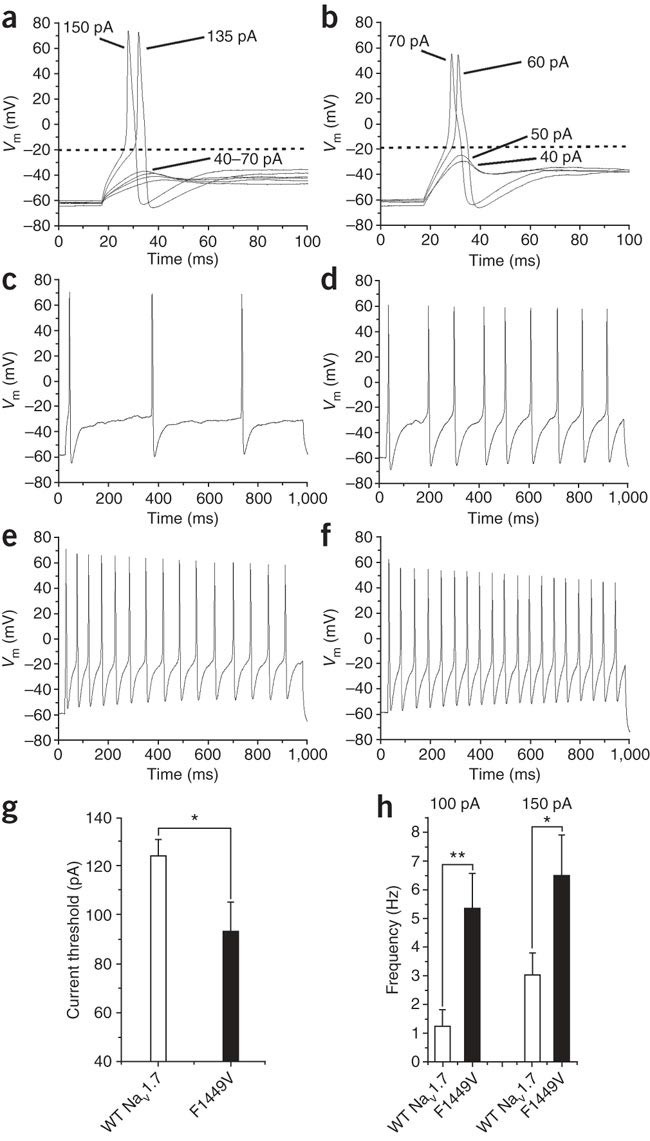
Action potentials were evoked using depolarizing current injections from a set holding membrane potential of −60 mV. (a) Representative traces from a cell expressing Nav1.7R showing subthreshold responses to 40–70 pA current injections and subsequent overshooting action potentials evoked by injections of 135 pA (current threshold for this neuron) and 150 pA, as labeled. (c) A representative DRG neuron, expressing Nav1.7R where 150 pA of current was injected for 950 ms, evoking three action potentials. The response of the same cell to 950 ms at 400 pA current pulse is displayed in panel e, showing that as expected, these cells are able to fire trains of action potentials. (b) In contrast, in a cell expressing F1449V, representative responses to 40–70 pA current injections are shown. Action potentials were evoked by >60 pA injections, showing a lower current threshold for action potential induction. Note that the action potential voltage threshold (dotted line) was similar for the neurons in panels a and b. (d) Demonstration of repetitive firing of action potentials in a small DRG neuron expressing mutant Nav1.7R in response to only 150 pA current injection for 950 ms. With a higher input of 400 pA, a similar pattern of firing was found in the WT channel (f) showing similar peak frequencies in these neurons. (g) Averaged current threshold for all cells tested. There is a significant (*P < 0.05) reduction in current threshold with the expression of F1449V (n = 19) when compared with cells expressing Nav1.7R (n = 16). (h) Frequency of firing in response to 100 and 150 pA current injections for 950 ms in those cells that showed multiple firing. There is a significant increase in the frequency of firing with the expression of F1449V (n = 12), in comparison with Nav1.7R (n = 9–11), at both 100 pA (**P < 0.01) and 150 pA (*P < 0.05) injection levels. (Some of these data were published previously in Dib-Hajj et al.37)
Timing Varies from 10–30 min
-
i
Critical Step
For successful voltage-clamp recording, the cells must also be healthy, display normal morphology and have as few projections as possible.
Critical Step
Inadequate space clamp is generally due to extensive neurites, which can be minimized by replating cells, limiting time in culture or using a substrate that inhibits neurite outgrowth. Problems with large voltage-clamp errors can be minimized by reducing current amplitudes (e.g., using lower external sodium concentrations), using lower resistance pipettes and using fast series resistance compensation.
-
A

Troubleshooting
Troubleshooting advice can be found in Table 1.
Timing
Step 1, prepare DRG cultures: 60–80 min; 1–3 days incubation time.
Step 2, transfer DRG cells to microscope stage: 1–5 min.
Step 3, prepare patch pipettes and solutions: varies between 10–60 min.
Step 4, visually select a cell for patch-clamp recording: 2–3 min.
Step 5, allow the GΩ seal to form then break-in to whole-cell mode: 1–2 min.
Step 6 (A or B), perform electrophysiological data recording: 5–20 min.
Anticipated results
Using these methods, it is possible to accurately describe the voltage dependence, kinetics and other properties (such as resurgent and persistent currents) of a sodium channel of interest, within a mammalian peripheral neuronal background. The main parameters to measure using the current-clamp recordings are relatively standard. The presence of any spontaneous firing can be noted and the input resistance measured by recording voltage changes evoked by injection of hyperpolarizing current. The rheobase (current threshold for action potential generation) can be calculated as the minimum amount of current applied for 100–200 ms that is required to produce an action potential. The action potential voltage can be measured at the beginning of the sharp upward rise of the action potential. Repetitive firing can be calculated from the recording of responses to sustained injection of depolarizing current for ∼1 s by simply counting the number of action potentials during each second to obtain the frequency of firing.
Analyzing data from voltage-clamp experiments involves measuring current densities, performing Boltzmann fits and fitting current traces with exponential or Hodgkin–Huxley type equations. However, the quality of the data depends on the quality of the voltage clamp and space clamp. These can be judged from the raw data (see Fig. 1). The maximum theoretical voltage error can also be simply estimated with the following equation:
Voltage error = (access resistance) × (1 – fraction series resistance compensation) × (currentamplitude)
Thus, a 10-nA current recorded with 80% series resistance compensation and a 1-MΩ access resistance will have a 2-mV maximum theoretical voltage error. Voltage errors ≤5 mV are generally acceptable.
Several other factors can introduce artifactual results. First, inadequate expression of channels may be an issue and can be checked using voltage clamp. Second, effects may already be saturated under control conditions, e.g., if an increase in action potential firing frequency is expected for cells expressing a mutant channel, then this may not be demonstrable if the control cells expressing the wild-type channel are already firing at their maximum frequency; changing the solutions to reduce the firing rate across all experimental groups may allow the phenomenon to be shown. Third, there may be a heterogeneous population of cells; selection of cells of the same type based on cell size or supravital staining may permit comparison of well-defined cell population. These methods can be used to study mutant as well as wild-type sodium channels, as illustrated by the examples provided above. These methods can also be used to study other ion channels, e.g., voltage-gated calcium and potassium channels, in mammalian neurons.
References
Raman, I.M., Sprunger, L.K., Meisler, M.H. & Bean, B.P. Altered subthreshold sodium currents and disrupted firing patterns in Purkinje neurons of Scn8a mutant mice. Neuron 19, 881–891 (1997).
Raman, I.M. & Bean, B.P. Resurgent sodium current and action potential formation in dissociated cerebellar Purkinje neurons. J. Neurosci. 17, 4517–4526 (1997).
Cummins, T.R., Dib-Hajj, S.D., Herzog, R.I. & Waxman, S.G. Nav1.6 channels generate resurgent sodium currents in spinal sensory neurons. FEBS Lett. 579, 2166–2170 (2005).
Akopian, A.N., Sivilotti, L. & Wood, J.N. A tetrodotoxin-resistant voltage-gated sodium channel expressed by sensory neurons. Nature 379, 257–262 (1996).
Djouhri, L. et al. The TTX-resistant sodium channel Nav1.8 (SNS/PN3): expression and correlation with membrane properties in rat nociceptive primary afferent neurons. J. Physiol. (Lond.) 550, 739–752 (2003).
Sangameswaran, L. et al. Structure and function of a novel voltage-gated, tetrodotoxin-resistant sodium channel specific to sensory neurons. J. Biol. Chem. 271, 5953–5956 (1996).
Choi, J.S., Dib-Hajj, S.D. & Waxman, S. Differential slow inactivation and use-dependent inhibition of Nav1.8 channels contribute to distinct firing properties in IB4+ and IB4− DRG neurons. J. Neurophysiol. 97, 1258–1265 (2007).
Dib-Hajj, S.D., Cummins, T.R., Black, J.A. & Waxman, S.G. From genes to pain: Nav1.7 and human pain disorders. Trends Neurosci. 30, 555–563 (2007).
Rush, A.M. et al. A single sodium channel mutation produces hyper- or hypoexcitability in different types of neurons. Proc. Natl. Acad. Sci. USA 103, 8245–8250 (2006).
Dib-Hajj, S. et al. Transfection of rat or mouse neurons by biolistics or electroporation. Nat. Protoc 4, 1118–1127 (2009); DOI: 10.1038/nprot.2009.90.
Marty, A. & Neher, E. Tight-Seal Whole-cell Recording (Plenum, New York, 1995).
Hamill, O.P., Marty, A., Neher, E., Sakmann, B. & Sigworth, F.J. Improved patch-clamp techniques for high-resolution current recording from cells and cell-free membrane patches. Pflugers Arch. 391, 85–100 (1981).
Molleman, A. Patch Clamping: An Introductory Guide to Patch Clamp Electrophysiology (John Wiley, West Sussex, UK, 2003).
Cummins, T.R. et al. Nav1.3 sodium channels: rapid repriming and slow closed-state inactivation display quantitative differences after expression in a mammalian cell line and in spinal sensory neurons. J. Neurosci. 21, 5952–5961 (2001).
Akopian, A.N. et al. The tetrodotoxin-resistant sodium channel SNS has a specialized function in pain pathways. Nat. Neurosci. 2, 541–548 (1999).
Fjell, J. et al. Differential role of GDNF and NGF in the maintenance of two TTX-resistant sodium channels in adult DRG neurons. Mol. Brain Res. 67, 267–282 (1999).
Leffler, A. et al. GDNF and NGF reverse changes in repriming of TTX-sensitive Na(+) currents following axotomy of dorsal root ganglion neurons. J. Neurophysiol. 88, 650–658 (2002).
Cummins, T.R. et al. A novel persistent tetrodotoxin-resistant sodium current in SNS-null and wild-type small primary sensory neurons. J. Neurosci. 19, RC43 (1999).
Herzog, R.I., Cummins, T.R., Ghassemi, F., Dib-Hajj, S.D. & Waxman, S.G. Distinct repriming and closed-state inactivation kinetics of Nav1.6 and Nav1.7 sodium channels in mouse spinal sensory neurons. J. Physiol. (Lond.) 551, 741–750 (2003).
Campbell, D.T. Single-channel current/voltage relationships of two kinds of Na+ channel in vertebrate sensory neurons. Pflugers Arch. 423, 492–496 (1993).
Motomura, H., Fujikawa, S., Tashiro, N., Ito, Y. & Ogata, N. Single-channel analysis of two types of Na+ currents in rat dorsal root ganglia. Pflugers Arch. 431, 221–229 (1995).
Rush, A.M., Brau, M.E., Elliott, A.A. & Elliott, J.R. Electrophysiological properties of sodium current subtypes in small cells from adult rat dorsal root ganglia. J. Physiol. (Lond.) 511, 771–789 (1998).
Roy, M.L., Reuveny, E. & Narahashi, T. Single-channel analysis of tetrodotoxin-sensitive and tetrodotoxin-resistant sodium channels in rat dorsal root ganglion neurons. Brain Res. 650, 341–346 (1994).
Coste, B., Osorio, N., Padilla, F., Crest, M. & Delmas, P. Gating and modulation of presumptive NaV1.9 channels in enteric and spinal sensory neurons. Mol. Cell Neurosci. 26, 123–134 (2004).
Saab, C.Y., Cummins, T.R. & Waxman, S.G. GTP(gammaS) increases Nav1.8 current in small-diameter dorsal root ganglia neurons. Exp. Brain Res. 152, 415–419 (2003).
Chen, Y. & Penington, N.J. Competition between internal AlF(4)(−) and receptor-mediated stimulation of dorsal raphe neuron G-proteins coupled to calcium current inhibition. J. Neurophysiol. 83, 1273–1282 (2000).
Coleman, D.E. et al. Structures of active conformations of Gi alpha 1 and the mechanism of GTP hydrolysis. Science 265, 1405–1412 (1994).
Murphy, A.J. & Hoover, J.C. Inhibition of the Na,K-ATPase by fluoride. Parallels with its inhibition of the sarcoplasmic reticulum CaATPase. J. Biol. Chem. 267, 16995–16700 (1992).
Ono, K. & Arita, M. Mechanism of fluoride action on the L-type calcium channel in cardiac ventricular myocytes. Cell Calcium 26, 37–47 (1999).
Partanen, S. Inhibition of human renal acid phosphatases by nephrotoxic micromolar concentrations of fluoride. Exp. Toxicol. Pathol. 54, 231–237 (2002).
Zeng, H. et al. Improved throughput of PatchXpress hERG assay using intracellular potassium fluoride. Assay Drug Dev. Technol. 6, 235–241 (2008).
Toledo-Aral, J.J., Brehm, P., Halegoua, S. & Mandel, G. A single pulse of nerve growth factor triggers long-term neuronal excitability through sodium channel gene induction. Neuron 14, 607–611 (1995).
Toledo-Aral, J.J. et al. Identification of PN1, a predominant voltage-dependent sodium channel expressed principally in peripheral neurons. Proc. Natl. Acad. Sci. USA 94, 1527–1532 (1997).
Rush, A.M., Cummins, T.R. & Waxman, S.G. Multiple sodium channels and their roles in electrogenesis within dorsal root ganglion neurons. J. Physiol. (Lond.) 579 (Part 1): 1–14 (2007).
Cummins, T.R., Dib-Hajj, S.D. & Waxman, S.G. Electrophysiological properties of mutant Nav1.7 sodium channels in a painful inherited neuropathy. J. Neurosci. 24, 8232–8236 (2004).
Cummins, T.R. & Waxman, S.G. Downregulation of tetrodotoxin-resistant sodium currents and upregulation of a rapidly repriming tetrodotoxin-sensitive sodium current in small spinal sensory neurons after nerve injury. J. Neurosci. 17, 3503–3514 (1997).
Dib-Hajj, S.D. et al. Gain-of-function mutation in Nav1.7 in familial erythromelalgia induces bursting of sensory neurons. Brain 128, 1847–1854 (2005).
Acknowledgements
We thank Dr. Jin Sung Choi, Dr. Xiaoyang Cheng, Lynda Tyrrell, Larry Macala, Shujun Liu, Rachel Blackman, Bart Toftness and other members of our groups for valuable assistance in development and refinement of the techniques described in this article. Work in S.G.W. Laboratory is supported in part by grants from the National Multiple Sclerosis Society and the Rehabilitation Research and Development Service and Medical Research Service, Department of Veterans Affairs. T.R.C. was supported by research grant NS053422 from the National Institutes of Health. The Center for Neuroscience and Regeneration Research is a Collaboration of the Paralyzed Veterans of America and the United Spinal Association with Yale University.
Author information
Authors and Affiliations
Corresponding author
Rights and permissions
About this article
Cite this article
Cummins, T., Rush, A., Estacion, M. et al. Voltage-clamp and current-clamp recordings from mammalian DRG neurons. Nat Protoc 4, 1103–1112 (2009). https://doi.org/10.1038/nprot.2009.91
Published:
Issue Date:
DOI: https://doi.org/10.1038/nprot.2009.91
This article is cited by
-
Sigma-1 receptor activity in primary sensory neurons is a critical driver of neuropathic pain
Gene Therapy (2022)
-
Bioresorbable thin-film silicon diodes for the optoelectronic excitation and inhibition of neural activities
Nature Biomedical Engineering (2022)
-
Functional alterations by a subgroup of neonicotinoid pesticides in human dopaminergic neurons
Archives of Toxicology (2021)
-
Conditional knockout of NaV1.6 in adult mice ameliorates neuropathic pain
Scientific Reports (2018)
-
MicroRNA-182 Alleviates Neuropathic Pain by Regulating Nav1.7 Following Spared Nerve Injury in Rats
Scientific Reports (2018)
Comments
By submitting a comment you agree to abide by our Terms and Community Guidelines. If you find something abusive or that does not comply with our terms or guidelines please flag it as inappropriate.
